As the number of products produced on tablet presses continues to grow and become more diverse, tablet press and tooling manufacturers have made many advancements in the field of tableting science. With product lines spanning many industries (pharmaceutical, chemical, energetic, electrical, food, and confectionery) the need for quality, well-engineered tooling is at an all-time high.
Recently, with the help of ever-advancing computer technology, the old textbook standard by which maximum compression force for various tablet configurations has been calculated is being re-examined and revised.
A quality tablet punch starts with quality tool steel. Many different types of tool steels are utilised in the tableting industry, each with unique and advantageous properties. An industry standard for many years, AISI S7 is suitable for many applications due to its excellent shock resistance and thus good resistance to splitting/ shearing stress and its ability to withstand relatively high compression forces.
Other tool steels such as AISI D2, DC-53, K340, and PM class steels offer excellent wear resistance due to their higher attainable hardness and increased carbide content. Tool steels with a higher chromium content, such as AISI 440C and M340 are particularly useful when pressing corrosive or sticky products. As a general rule, as the Rockwell hardness of a material increases, the wear resistance increases but the impact toughness decreases.
However, some of the PM class steels have both excellent wear resistance and relatively high impact toughness due to their unique chemical composition and distinctive forging/manufacturing process. Quality tool vendors offer a variety of tool steels so that the optimal steel can be selected that exceeds the requirements for desired compression force and different granulations’ abrasive, sticky, or corrosive properties.
When calculating maximum tip force for all tool steels, the properties that must be taken into consideration are impact toughness, compressive strength, tensile strength, and most importantly yield strength. Impact toughness is relative to the maximum amount of energy from an impulse or shock loading condition.
Compressive, tensile, and yield strength are relative to the chemical composition of the steel and the Rockwell hardness. Compressive strength is defined as a materials resistance to deformation in pure compressive loading. Tensile strength is the maximum stress the material can undergo when being pushed or stretched before failing. Finally, yield strength is the maximum amount of stress a material can withstand before plastic deformation occurs. It is because of the unique and distinct mechanical properties of various materials that the maximum compression forces are different for the various tool steels.
During the compression phase of the tableting process, forces act normal to all surfaces of the cup (figure 1). These forces result in stress, which is a function of both cup area and geometric profile. Basic stress is relative to the force exerted and the area over which it is applied. The comparison of maximum stress to the yield strength of a given material is the basis for calculating maximum allowable compression force. In addition to force and area, stress concentration factors must also be considered when determining maximum compression force.
A stress concentration is a small area of significantly increased stress induced by a sharp transition in the geometric profile of the cup/ punch face, such as a bisect or the blend radius where embossing meets the cup radius. These stress concentrations and their consequential increased stress result in lower maximum compression forces than their plain tablet counterparts.
In addition to the geometric profile of the cup and the presence of bisects and/or embossing, the land on a punch face also plays a very critical role in determining the maximum allowable compression force. The land is the flat edge around the perimeter of a punch cup where the cup radius ends. This seemingly small feature of tablet design plays a very significant role in the maximum force a punch tip can withstand.
As a general rule, the greater the land on a tablet or tool, the greater the maximum allowable compression force. Increasing the land on almost any given tablet design is one of the easiest and quickest ways to increase the maximum compression force. It is important to note that as tooling wears, the land begins to erode and become smaller and smaller. This worn land would mean that the same punch could withstand more force when brand new than when it has been used for many production runs.
This is one of the reasons why proper tooling maintenance is so important because not only does it ensure quality tablets but also helps to maintain the mechanical integrity of the tool itself.
A powerful engineering tool that is becoming increasingly useful in many different fields and industries is Finite Element Analysis (FEA). This computer software allows engineers to apply any combination of forces and/or pressures to a solid model and view the resulting stresses, strain, displacement, and factors of safety associated with any part or assembly. This type of analysis is useful in the field of tableting science as it allows one to analyse complex cup geometry and view where stress concentrations (areas of much higher stress states than their immediate surroundings) result, thus improving tablet and tool design.
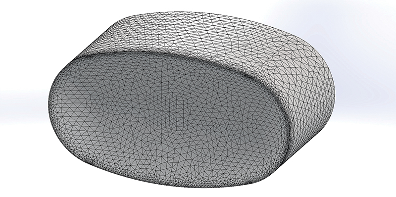
Figure 2. Meshed model
FEA works just as its name implies, by analysing a larger model on a much smaller piece-by- piece scale. First a model is broken down into a finite number of small pieces, the size of which is controlled by the user; this is known in the FEA environment as a mesh (figure 2). Next a material, with all necessary properties defined, is assigned to the model. The desired force vectors are then applied to all applicable surfaces. The model is then constrained to simulate its allowable movement in its real world installed application. Lastly, a failure criterion must be selected. In layman’s terms, this means the criteria by which the material and part combination is likely to fail. With these parameters in place the analysis is performed; the FEA software analyses the stress states of the model for each element in the mesh. This returns a very detailed result of where maximum stress and resulting failure is likely to occur, and consequently which areas are in need of design modifications.
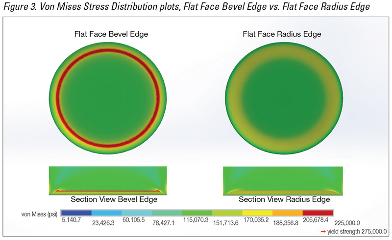
Figure 3. Von Mises Stress Distribution plots, Flat Face Bevel Edge vs. Flat Face Radius
For ductile materials, such as metals, Von Mises Stress is generally accepted as the best failure criterion. Von Mises Stress (a.k.a. equivalent tensile stress) states that when subjected to three-dimensional loading conditions, any elastically deformable body will develop a complex three-dimensional system of stresses. The Von Mises Yield criterion states that even though none of the three principal stresses exceed the yield strength, yield may still occur as a result the combination of the stresses. This criterion works particularly well in finite element analysis because a meshed model has almost an infinitely large number of degrees of freedom, and the calculated Von Mises Stress combines all stresses into an equivalent tensor value that can be compared to the known yield strength of the material. It now needs to read: Figure three shows the Von Mises Stress Plots of a flat face bevel edge compared to a flat face radius edge punch tip. Note the stress concentration (red area) on the bevel edge tip where the bevel meets the flat of the cup.
It is also important to note that the maximum compression force listed on the tablet and tool drawings considers fatigue life of the tooling. Most of the time tablet compression tools are used to produce thousands if not millions of tablets. As the compression tooling undergoes repeated loading cycles during tablet production, residual stresses build up over time. This phenomenon is known as fatigue stress and can shorten the life of the tooling. The maximum force the punch can withstand decreases over time due to wear on the tooling and the build-up of residual stress. This means that the tooling can withstand more force when pressing the first tablet than it can when pressing the 500,000th tablet. Tooling produced at Natoli Engineering Company is designed and engineered for high cycle loading conditions.
There is one last factor that must be considered when considering max compression force and that is bending of the lower tip straights. Usually this is a concern for very small tip tooling, generally 4mm and smaller. When the tips are this small, most of the time the geometry of the cup is not the limiting factor when determining max compression force. The limiting factor is the propensity of the lower tips to bend under the compressive load. For these small tipped tools, the max compression force is determined by calculating the compressive load required to bend the tips.
After all these factors are taken into consideration, the appropriate max compression force is determined by comparing the calculated stress and force results to what is considered an appropriate Factor Of Safety (F.O.S) for the given application. Simply put the F.O.S. is the ratio of the calculated stress to the yield strength of the material. For example, a Factor Of Safety of 2 means that the force applied generates a stress in the material that is ½ the yield strength of the material. Different industries use different Factor of Safety’s for different engineering applications. In the tablet compression industry the major reason for varying max compression forces between different vendors is what a particular vendor considers an acceptable Factor Of Safety.
The combination of the various advantageous steel choices combined with the power of FEA software and the consideration of the many factors that affect tooling life result in tool and tablet designs where the max compression force calculations guarantee a quality tablet and smooth press operation from the first tablet to the last.
Kevin Queensen started at Natoli in 2011 after graduating with a Mechanical Engineering degree. He spent 4.5 years in the Engineering dept, then moved to the technical service depth. His areas of expertise include specialty tablet and tool design, FEA (finite element analysis), and troubleshooting tablet production related issues.