Although inline degassing prevents the majority of issues concerning solvent outgassing, it does not address all the challenges associated with dissolved air in the mobile phase. Recent research and development (R&D) efforts have focused on redesigning degassers to improve their efficiency and keep pace with LC and high-performance liquid chromatography (HPLC) technology innovation.
Saba Jazeeli, Senior Product Manager at IDEX Health & Science, talks to Dr Kevin Robinson about the impact that new degassers could have on analytical laboratory efficiency.
KSR: There are many variables that influence the analytical performance of HPLC systems. Can you outline the drawbacks of dissolved air in the mobile phase, something that has long been a challenge for chromatographers?
SJ: When solvents come into contact with the atmosphere, air — composed primarily of oxygen and nitrogen — gradually dissolves into the solvent. When the aqueous and organic solvents are mixed, they each contribute to the total dissolved air content of the mixture, and each gas has its own individual properties that impact the HPLC experiment in various ways.
Most commonly, pumps and detectors are affected by outgassing (when dissolved air bubbles out of the solution), causing flow and mixture inaccuracies. Additionally, dissolved oxygen affects optical detector performance by forming a UV light-absorbing complex with many solvents that absorb light passing through the flow cell, causing noise spikes in the chromatogram and obscuring or creating false analyte peaks.1
The degree of these effects caused by dissolved gas in the mobile phase depends on both the solvents used and the oxygen concentration of the solvent.
The impact of outgassing on an HPLC experiment also depends on the type of mixing system: low pressure, which mixes solvents before the pump using a proportioning valve, or high pressure, which mixes solvents after the pump.
Low pressure mixing systems are more susceptible to bubble formation, as the mixed mobile phase is supersaturated before it reaches the pump and outgassing is initiated in the low-pressure region between the proportioning valve and the pump inlet. Nucleation sites and inlet check valves can further cause bubble formation owing to nucleation and turbulence.
Although high pressure mixing systems use a separate pump for each solvent, mixing occurs ahead of the injection valve and there is potential for cavitation and malfunction of the inlet check valve of each individual pump, especially in the case of gravity operated check valves. Additionally, because mixing takes place at high pressure, any dissolved gas will remain in solution until the pressure drops, which occurs after the mobile phase leaves the column.
Outgassing before the mobile phase enters the detector or the detector flow cell can cause errors in detection owing to increased baseline noise … and even from false peaks. Reducing the dissolved air from the mobile phase is therefore crucial to the stability of both low and high pressure HPLC system flow rates, as well as to mobile phase composition and the accurate identification of separated compounds.
KSR: Most labs currently use a tubular-based inline vacuum degassing system. Can you provide some insight into the early degassing solutions and why tubular-based systems have emerged as the gold standard?
SJ: Owing to the challenges presented by dissolved gases in the mobile phase, degassers are an important component of HPLC systems and have historically used a range of technologies, including vacuums, ultrasonics and gas sparging. Early work by Junji Tokunaga, published in 1975, outlined the Ostwald coefficients for the solubility of oxygen and nitrogen in various alcohol-water mixtures.2
This pioneering work demonstrated the degree to which methanol plus water mixtures need to be degassed to prevent bubble formation and formed the foundation for today’s inline degassing for HPLC solvent mixtures.
Practiced since the late 1970s, helium purging — a gas sparging approach in which helium is bubbled through the solvent — can remove up to 80% or more of dissolved air when practiced correctly, but the rising cost and decreasing availability of helium limits the widespread applicability of this method.

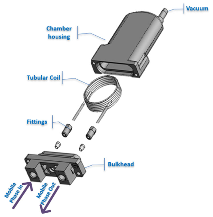
Figure 1: An inline tubular vacuum degasser
However, the loss of volatile components during helium sparging contributes to concentration changes within premixed mobile phases. Bulk mobile phase sonication using ultrasonic baths only removes up to 60% of the gas and is highly variable. Bulk vacuum degassing exposes the mobile phase solvent to a vacuum and the reduced pressure removes more than 60% of the dissolved air and, like helium sparging, will change the concentration of a premixed mobile phase.
Inline vacuum degassers comprised a gas-permeable tube or membrane through which the mobile phase passes and a vacuum chamber (Figure 1). When vacuum is applied on the outside of the membrane, dissolved gas passes and diffuses through the membrane and the liquid mobile phase remains inside. Most inline vacuum degassers make use of either Teflon AF or polytetrafluoroethylene (PTFE) as a membrane material.
KSR: Tubular-based degassers have now been in use for some time. Are there any alternative devices that produce the same, if not better, results?
SJ: As most HPLC systems have integrated degassers, their longstanding functionality means that models have remained largely unchanged for decades. However, recent improvements in vacuum degasser flow channel design are enabling users to achieve higher efficiency degassing in a more streamlined device that economises the use of crucial materials (such as Teflon AF).
All current HPLC degassers operate at a single fixed setpoint for the applied vacuum of all methods and flow rates. This value has typically been set to 50 mmHg absolute pressure, but other pressure/vacuum levels are also used.
Vacuum degassing systems that are set to a single high vacuum setpoint (such as 50 mmHg) are designed specifically to meet the degassing requirements of the upper flow rate range of the individual HPLC system and all channels are set at one vacuum level.
Additionally, current systems make use of as many as six vacuum degassing channels; so, irrespective of the system flow rate, there will be variable efficiencies and unnecessary demand on the vacuum pump. The ability to vary the vacuum applied to the chambers by the vacuum pump not only relieves this demand, but will ensure the constant performance of HPLC separations.
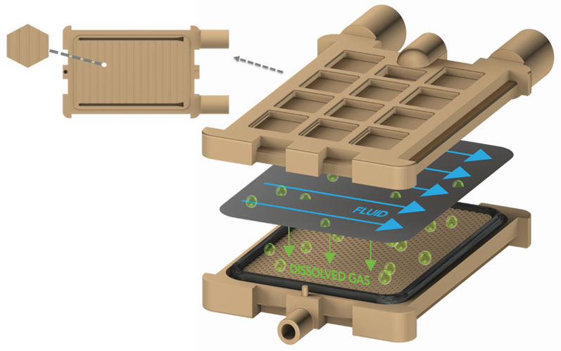
This level of control is possible using the new control methodology, along with the film degasser, to provide constant performance across almost the entire flow rate range of the HPLC system. Liquid flows across a Teflon AF film in a thin layer, then dissolved gas migrates through the degassing film (Figure 2).
Simplifying the complex and variable design elements of tubular-based vacuum degassers, such as membrane wall thickness, tubing ID (fluid diffusion path) and length of the tube, will improve efficiency and impact flow restriction.

Figure 2: Schematic of a new flat film membrane degasser
KSR: What are the advantages of flat film technology?
SJ: There are two diffusion paths involved in inline degassing (ignoring vacuum side diffusion). First, dissolved gasses in the mobile phase must diffuse to the surface of the membrane or film. Second, the dissolved gasses must diffuse through the membrane (flat film or tubing wall).
Reducing the diffusion path to improve degassing efficiency is challenging in tubular-based membranes. If the wall is too thin, the degassing coil will kink during manufacturing. If the diffusion path in the fluid is reduced by reducing the ID of the tubing, flow restriction increases dramatically.
A key advantage of new film membrane degassers is the ability to create a shorter diffusion path in both the fluid and the membrane (flat film). Additionally, by reducing membrane wall thickness, the amount of Teflon AF used in the device is minimised, improving the cost-effectiveness of the device.
Currently, optimal degassing solutions achieve a level of performance, for the maximum flow rate of the HPLC system design, using a single setpoint of applied vacuum. Ideally, a single degassing system would meet two universal goals. First, a single type of the degassing channel should have enough performance to meet the requirements of any analytical-scale HPLC system.
Second, the degassing system should minimise the movement of solvent vapours across the membrane — a phenomenon known as pervaporation — to reduce concentration changes in mixed mobile phases and, at the same time, minimise the amount of solvent vapour discharged into the laboratory atmosphere.
Users are restricted by the intricacies of tubular-based degasser design, such that several iterations with a specific combination of parameters are needed to optimise HPLC system performance. The universality and flexibility provided by flat film degassers, as a single solution, eliminates the need for multiple vacuum chamber designs for various HPLC applications and improves performance consistency.
Additionally, in terms of practical use, the simple design of a flat film degasser’s internal fittings or connections minimises the likelihood of system failure and improves the integrity of the device.
KSR: How will this new technology impact analytical labs and the future of degassing in HPLC experiments?
SJ: The primary goal of any analytical laboratory is to safely optimise processes and improve efficiency. Productivity gains can be achieved across the HPLC workflow through the highly effective, thinner flat film membrane degasser technology, and controlling the discharge of solvent vapours into the atmosphere can lower the lab’s environmental impact.
Additionally, most laboratories face space limitations, so the compact design of flat film devices aligns with the need for increasingly smaller instrument footprints. The introduction of flat film membranes into the market represents a significant step forward for the industry and is likely to improve the efficiency of analytical laboratories in the future.
References
- S.R. Bakalyar, M.P.T. Bradley and R. Honganen, “The Role of Dissolved Gases in High-Performance Liquid Chromatography,” Journal of Chromatography A 158(1), 277–293 (1978).
- J. Tokunaga, “Solubilities of Oxygen, Nitrogen and Carbon Dioxide in Aqueous Alcohol Solutions,” J. Chem. Eng. Data 20(1), 41–46 (1975).
