Water For Injection (WFI) has to meet certain standards for sterility and clarity and its manufacture must, therefore, begin with purified water, i.e. water that has already undergone standard reverse osmosis treatment, demineralisation, electro-deionisation or an equivalent process, and subsequent distillation.
Distillation is the only process for the manufacture of WFI recognised by the European Pharmacopeia, although the US Food and Drug Administration (FDA) also recognises WFI production by double reverse osmosis.
Haupt Pharma began a project to refurbish its WFI production in 2006. The old installation was equipped with electric distillers that, for economic reasons, functioned only during the night producing WFI that was held in storage tanks for use during the day.
The installation had various disadvantages:
- It created difficulties when working to a three shifts system;
- Output was limited during the day;
- Final rinsing of the empty ampoules could not be carried out with WFI;
- It was not possible to have a temperature lower than 25°C when needed;
- The electricity cost was high and, technically, the installation was no longer state-of-the-art (it produced few data records and had few control devices on line).
The quality of the WFI was, however, always fully compliant with EP standards.
Haupt Pharma therefore considered the design of a new installation for WFI production with a distiller running continuously on industrial steam. In this instance, operation of the distiller for the purposes of WFI would be controlled in the storage tank. This operating mode, which is used widely today in the pharmaceutical industry, allows for production of WFI during the night, when required.
The user requirements were first defined with the quality, production and maintenance departments.
All the points of use, including the locations, flows and temperature, were determined. The request from the production department was to produce enough WFI to allow production for three shifts of eight hours, six days a week and 46 weeks a year. Daily consumption was evaluated every 15 minutes for each point to define the design of the installation.
Haupt Pharma also chose the design of the control panels for each sampling point during this phase of the project. The distiller was to be a multi-effect system running on industrial steam and would be fed with purified water, producing WFI in sufficient quantity for the production.
The purified water to feed the distiller would be produced by reverse osmosis (RO), coupled to an electro-deionisation (EDI) unit followed by a tangential ultra filtration device. This installation already existed and a sampling point for the distiller was to be added onto the loop. With this water treatment equipment, the water that feeds the distiller has a quality equivalent to that of WFI.
The storage tank was to be fitted with a filter vent equipped with an electric heater (to prevent condensation in the filter); its dimensions were selected for complete mixing of the tank, and a range of between one and five renewals per hour.
The loop, the tank, the heat exchangers and the sensors were all to be made of 316L stainless steel (1.4435BN2, Ra< 0.6µm, electro polished).
The exchangers are of the multitubular type. The dimensioning of piping was defined to allow a flow between 1 and 3m/s wherever on the loop. The sampling point is of the ‘zero dead leg’ type and includes a sample point integrated into the valves and permanently connected to the machines (see Fig. 1).
The loop would be maintained at 85°C but one part could be cooled temporarily to 20°C when needed (see Fig. 3). Equipment was to be installed on each return of the loop to enable monitoring of total organic carbon (TOC), conductivity, flow, pressure and temperature.
Automated heat treatment of the installation with superheated water at 121°C has also been set up for the tank and the loop. The filter vent and piping between tank and distiller will be sterilised by the steam generated in the top of tank by superheated water.
tight on space
One of the main technical problems encountered was the installation of the distiller, storage tank and skid hydraulic in the only room available for this equipment – which was going to be a tight squeeze. The dimensions of the room as well as access were integrated into the User Requirement Specification. To ensure successful installation, the distiller was designed such that it could be delivered in three parts and the storage tank and the hydraulic skid were made to measure.
One of the most important parameters of this project was to minimise production stoppages. With this in mind, Haupt Pharma found a room to accommodate the new distiller and its storage tank, where they could be installed without stopping the existing unit. The new loop was therefore set up in parallel with the old one, and any of the parts of the process that necessitated a shut-down were installed during the 2007 Christmas holidays.
Connection of the equipment was carried out during the 2008 summer break – after commissioning and the first phase of qualification – and that required two weeks of stoppage.
three-year timetable
The whole project, which took approximately three years (including a year of Performance Qualification), was carried out according to the following schedule:
- September 2006: determination of requirements in terms of consumption of water and listing of the points of use and definition of essential operating parameters; also user requirements specification with the assistance of a consultant
- Spring 2007: communication of essential operating parameters and user requirements specification to the suppliers
- Summer 2007: suppliers and providers chosen
- September 2007: orders placed with suppliers
- October 2007: beginning of the set-up (water loop, electric wiring, etc.)
- March 2008: FAT of the hydraulic distiller/skid/storage tank/electrical equipment box/software and delivery of the distiller in three parts and set up of the storage tank
- May 2008: Qualification of the distiller
- June 2008: Delivery of the skid hydraulic and first feeding of the installation with water
- July/August 2008: Qualification of water loop and storage tank and connection of the loop to the production equipment
- September 2008: Start of production with new WFI loop. Start of the last phase of QP
- September 2009: End of the QP
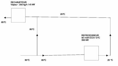
At the beginning of the project, Haupt Pharma wanted to find solutions that would reduce the energy impact of such an installation. One of the highest energy-using aspects of the system is the temporary passage through part of the loop where the temperature is reduced from 85°C to 20°C via a heat exchanger connected to cooling equipment, and then its reheating to 85°C before returning into the storage tank.

Fig: 2: Diagram of Haupt Pharma’s old WFI heating and cooling system
energy savings
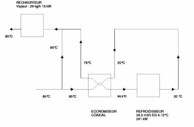
To limit the size of the cooling equipment and electricity consumption, Haupt Pharma chose to install a multi-tube heat exchanger. This equipment also makes it possible to reduce the consumption of steam used to heat this water from 20°C back to 85°C before its return to the storage tank (see Figures 2 and 3). The system offers a 30% reduction in cooling and 90% reduction in steam consumption compared with a conventional heat exchanger. This multi-tube exchanger is particularly innovative and has to be manufactured to a very high specification. It requires the same surface quality (Ra< 0.6µm electro polished) for the tube both inside and outside; generally a tube containing WFI only needs such a surface on the inside. The added expense of this equipment was compensated for by the reduced size of the cooling equipment necessary to cool the WFI.

Fig: 3: Diagram of the newly installed, more economic system
back-up system
At the beginning of the project, Haupt Pharma wanted to have two systems – one of which would be a back-up – incorporated into this installation. The network architecture for the supervision and filing of the data consists of two servers and two supervision stations.
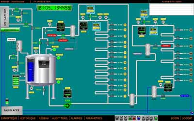
Automation of the WFI distribution and the distiller (using two different software programmes) is achieved through connections to the servers, which communicate together on a permanent basis. If one of the servers stops, the system switches automatically to the other; an alarm will show up on the supervision system and will also be sent to the guardroom in the event of defect, 24/7.

Fig. 4: View of the control panel screen for the automated WFI system. If one of the servers stops, the system switches automatically to the other and an alarm will show up on the supervision system
The two supervision stations, located in different places within the injectables building, also make it possible to connect to the system remotely from the plant. The supervision system conforms to the standard CFR21 part 11.
Following subsequent audits, the feedback from customers has been very positive. Both the quality results and the technical decisions made have satisfied the auditors. Internally analytical and microbiological results have been excellent and correspond to company expectations. The continuity of service has also conformed entirely to the User Requirement Specification.
About the author:
Lionel Bouvier has worked for Haupt Pharma Livron since 2000. He was the project leader for the new WFI loop and since January 2009 has become general maintenance manager. Haupt Pharma Livron is a CMO, based in France and specialising in sterile (aseptic filling and terminal sterilisation) and in suppositories.
