There’s a wealth of comprehensive information shown on an official, vendor-supplied tablet drawing, so deciphering these prints is essential to gain additional product insight. Upon customer request, reputable tooling vendors will supply tablet manufacturers with highly accurate tablet and tool drawings for each of their products.
Tablet drawings
A tablet drawing can provide an abundant amount of information for an individual who understands how to read a technical drawing. Each tablet design has its own unique properties that are displayed within the drawing. Most tooling vendors use a standard format or title block for each drawing created.
The title block includes the tablet description, recommended maximum compression force ratings for tooling, engineering data and much more. Figure 1 represents a typical drawing of a round tablet that you might receive from your tooling vendor.
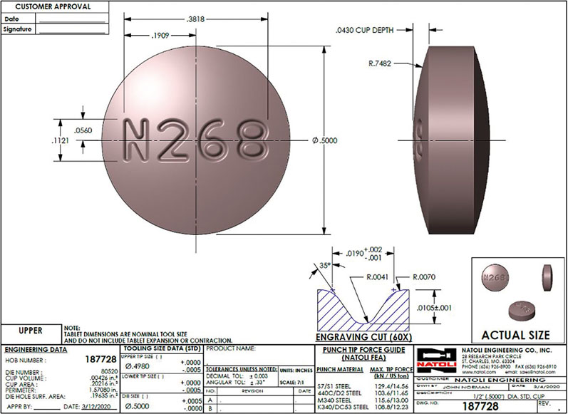
Figure 1: A typical drawing of a round tablet
Tablet drawings contain multiple views to completely display a tablet’s configuration. For round tablets, normally only two views are shown (top and side). Shaped tablet drawings commonly display three views to accurately represent a tablet’s geometry (top, end and side).
Figure 1 shows a typical round tablet, whereas Figure 2 displays a typical shaped tablet. The top view displays the cup face of the tablet; it may be plain or have a logo or tablet identifier present. Most drawings are created at a scale that’s larger than actual size to easily see the details associated with the design.
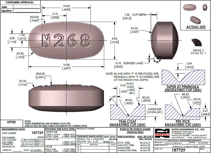
Figure 2: A typical drawing of a shaped tablet
As you can see in the Figures, there is an area dedicated to the drawing scale (centre area of the title block) and a display area for actual-size views of the tablet (provided the drawings are printed at full size).
How does understanding a tablet drawing help me?
Knowing how to read and understand a tablet drawing is beneficial for many colleagues within your company. Tablet drawings provide a visual representation of the appearance of the tablet’s geometry, including size, shape, cup configuration, identification (logo, etc.), breakline (if present) and engraving cut details (if applicable).
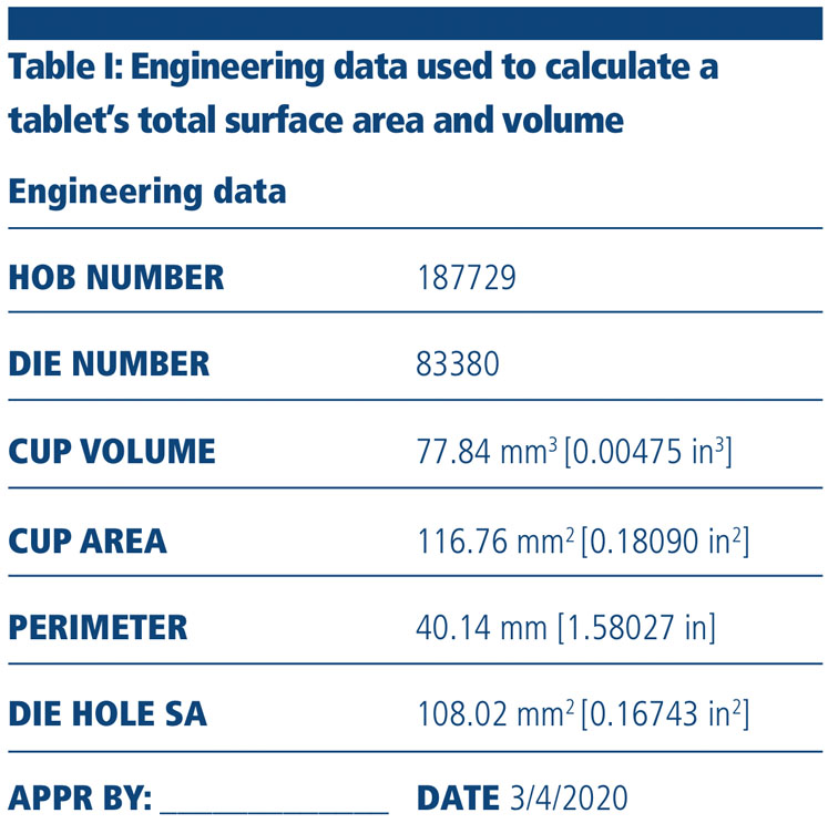
In addition, in research and development, the engineering data shown in Table I can be used to calculate a tablet’s total surface area and volume. Using the supplied data and knowing a tablet’s actual thickness allows you to compute these values.
This may be beneficial when creating a generic duplication of a brand name tablet or calculating dissolution rates or spray rates when film coating. Provided below are the steps required to calculate the total surface area and volume of a tablet.
Total surface area
- Take the “cup area” from the drawing and double it (there are two cup faces per tablet)
- Then, take the tablet “perimeter” from the drawing and multiply this value by the thickness of the “belly band” (belly band = overall thickness – two x cup depth or measure the belly band thickness by some other accurate means)
- Add step 1 and step 2 together to get the total surface area.
Total tablet volume
- Take the “cup area” from the drawing and double it (there are two cup faces per tablet)
- Then, take the “die hole surface area” from the drawing and multiply this value by the thickness of the “belly band” (see above); this is the volume of the centre part of the tablet
- Add step 1 and step 2 together to get the total volume
If you need assistance calculating these values, feel free to contact your tooling vendor. Understanding a tablet drawing is also useful during press configuration. When an operator is setting the safe maximum compression force or the overload value on a press, it’s necessary to know what force the punches are rated for.
The overload system should be set at or below the force rating provided to protect the punches from damage owing to accidental overload. Table II shows the force ratings for tablet drawing #187729 (see Figure 2) for the common punch steels frequently used in the tableting industry.
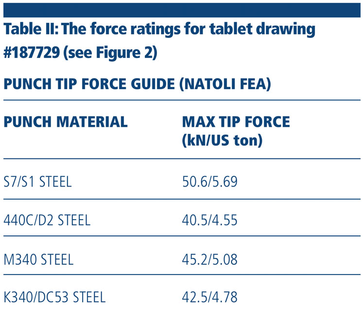
Each tool steel has a unique chemical composition, which results in different allowable force ratings. To find the tip force rating specific to a tooling set, refer to your vendor-supplied punch drawings. There’s a common misconception regarding the tip forces provided with these drawings.
Some may believe the compression force value provided is the force necessary to compress the tablet. However, you should only use the amount of force necessary to create a tablet that meets your acceptable parameters. Applying more force than the necessary to the punches may shorten the service life of your tooling.
Dimensions and tolerancing
Each technical drawing should have a tolerance block included in the format of the drawing. All tablet drawings should have an acceptable tolerance range applied to the dimensions of the model unless otherwise noted for a specific dimension.
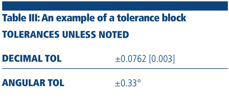
Table III is an example of a tolerance block that could be incorporated into any technical drawing with known dimensions. The tolerances shown within this area apply to the drawing dimensions if no specific tolerance is provided on any of the individual dimensions.
Looking at Figures 1 and 2, there are no specific tolerances associated with any of the dimensions on the drawings (except on some of the engraving cut sections), so the tolerance block notes the tolerance range for all other shown dimensions.
Learning more about your tablet design
When creating formal tablet drawings for a customer, tool vendors may dimension the models in one of three ways. In the US, most companies are satisfied with inch only dimensioning (see Figure 1). There are some companies that prefer to use metric dimensions and others opt to receive their drawings with dual dimensions (see Figure 2).
With both the inch and metric dimensions displayed on the drawing, any of your colleagues should feel comfortable reading the drawing no matter which unit of measurement they prefer. Inform your tooling vendor about the dimensioning scheme that works best for you and the drawing can be tailored to suit your needs.
Tablet logos/identifiers, engraving cuts and modifications
Products that encompass a logo or tablet identifier will include engraving cut details on the drawing. These detailed cross-section views will depict the width, depth, angle and radii values used to create the engraved feature(s) on the tablet face. Typically, the width and depth dimensions will be toleranced.
When designing a new product, always make your tooling vendor aware if the tablet will be film coated. If the final product is coated, there are modifications that must be made to the engraving cut design to help these features coat properly. Changing the draft angle, blend radii and engraving cut depth are a few of the variables that should be modified to help improve the film coating of a product and/or visibility after coating.
Figure 1 shows a tablet design that has a standard (non-coated) engraving cut, whereas Figure 2 shows a film coat engraving cut. For a film coated tablet, it is suggested to have a wider and deeper stroke and wider engraving cut angle for better exposure of the logo/identifier to the coating spray pattern.
Non-coated and film coated tablets have many variables that can be modified to customise the engraving cut for a particular application. Non-coated tablets are frequently designed with an engraving cut angle of 30–35 degrees (measured from vertical), whereas film coated tablets typically have a 35–45 degree angle.
Film-coated tablets may pose challenges during coating if the engraving cut is improperly designed. Increasing the blend radii from the engraving cut to the cup surface of the tablet is beneficial when a product is coated.
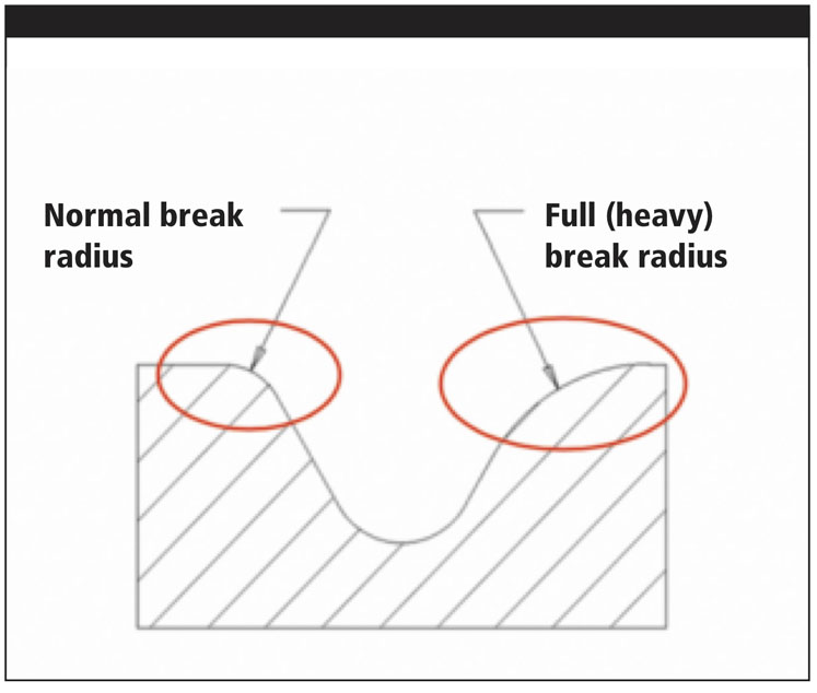
Figure 3: A standard and heavy break radius on the same engraving cut detail
The increased radii help with the coating application in these transition areas and prevent coating solution from saturating a sharp transition point that may erode away during this process (Figure 3).
Special modifications to the engraving cut design may be present in some cases. Prepick and taper may be added to a tablet design when picking within the logo is a concern. When prepick and taper is applied, there will be additional cross-section views on the drawing showing the amount present.
Figure 2 shows the additional engraving cut details you would see if this modification was present on your tablet design. Frequently, these features will be called out with a note on the drawing to describe where the prepick and tapering features are applied. In this case, the islands of the “6” and “8” are 30% prepicked, and the peninsulas of “N”, “2” and “6” are 30% tapered.
Tablet land and why it’s beneficial
Most tablet designs will incorporate a flat area around the periphery of the shape known as land. This feature is highly recommended to strengthen the punch tip edges and extend the service life of your punches. Looking at Figure 2, you will notice a dimension labelled BLENDED LAND.
The land is blended to eliminate the sharp transition between the cup curvature and the inner edge of the land where stress risers would result during tablet compression.
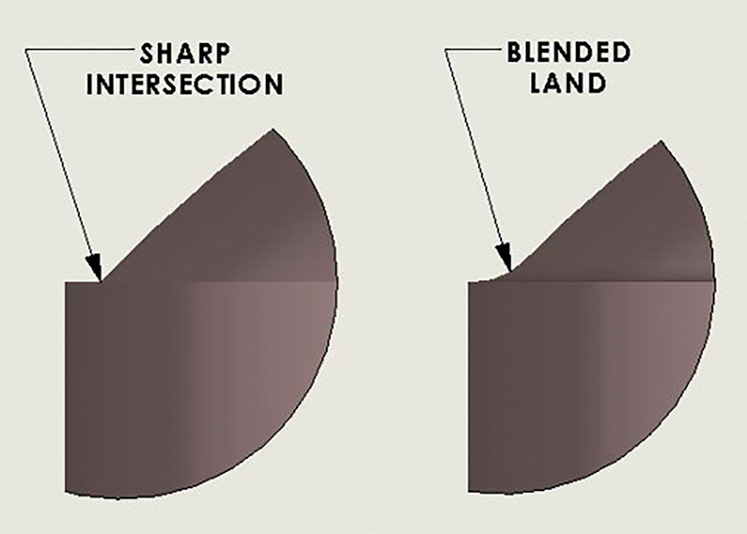
Figure 4: A tablet design that has no land blending (sharp intersection) next to an example of a blended land
Often, tooling vendors are asked by customers to reduce or remove land from a tablet design when a product is to be film coated. Decreasing the land amount is not the best way to approach this potential issue as it compromises the strength of the punch tip edges. Optimising the coating machine parameters to coat a tablet with blended land would be a reputable tooling vendor’s recommendation (Figure 4).
Conclusion
Understanding the technical drawings provided by your tooling vendor is crucial when learning more about the product you’re manufacturing. Contact your tooling vendor with any questions or tablet defect concerns regarding your current design. Reputable tooling vendors will be staffed with knowledgeable tablet design experts that may suggest changes to a tablet’s configuration to resolve common issues.